400G QSFP-DD Transceiver Wiring Scheme in 400G Data Center
The optical connection inside the data center needs to be realized with the help of optical modules and optical fiber connectors. In order to cope with the growth of data traffic and to take into account more flexible expansion and upgrade and backup functions, the new generation of large data centers has generally started to adopt leaf ridge network architecture, with more data exchange and throughput capacity inside the data center, as well as a flatter network structure.
For the optical modules interconnected in the data center, the corresponding optical module scheme needs to be selected from the cost consideration. For some TOR servers corresponding to the ridge architecture of the data center to the Leaf Layer and from the Leaf Layer to the Spine Layer, medium and long-range optical modules need to be used for data exchange. For 400G medium and long-range optical modules, there are mainly three schemes, 400G DR4, 400G FR4, and 2x200G FR4.
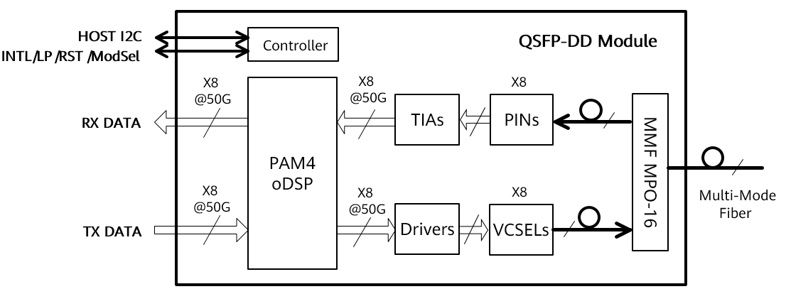
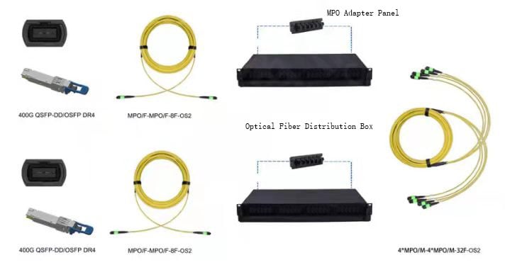
- 400G DR4: This module uses 100G PAM4 modulation technology with the 4-channel optical parallel transmission, so the 400G QSFP-DD DR4 optical module requires 8-core single-mode fiber. 400G DR4 optical module has a transmission distance of 500m, and the upgraded 400G DR4+ optical module can support 2km transmission. 400G QSFP-DD DR4 optical module is actually a 4x100G optical module, 400G DR4 optical module can be used as a 400G to 400G point-to-point connection or separated into 400G to 4x100G connection. In addition, the 400G DR4 can carry out flexible network wiring from 100G to 400G according to the port rate requirements of the customer’s data center, which can further save device bandwidth resources.

- 400G FR4:Different from the 400G DR4 structure, 400G QSFP-DD FR4 contains internal optical wavelength division components, also using 100G PAM4 technology. The 400G FR4 optical module uses wavelength division devices to multiplex the optical wavelength of CWDM4 to a single-mode fiber for transmission. Therefore, the 400G FR4 optical module only needs two single-mode fibers. 400G FR4 supports 2km transmission. The 400G FR4 optical module can only be used as a 400G optical module for a point-to-point connection, and it contains optical wavelength division elements, so the overall module cost of 400G FR4 is higher than that of 400G DR4. Moreover, because it can only be used as a 400G point-to-point connection and does not have flexible connectivity, it is more appropriate to use it only in some scenarios that require high-speed ports.
- 2x200G FR4:This optical module has two sets of 200G CWDM4 2km optical modules inside, so in essence, the 2x200G FR4 optical module is functionally a 200G optical module. 2x200G FR4 uses 50G PAM4 modulation technology, and the device requirements are not much different from those of 100G optical modules. Therefore, when the optical chip and electric chip industry chain is not mature enough and the end customers need to upgrade the network port, 2x200G FR4 is a better transition scheme.
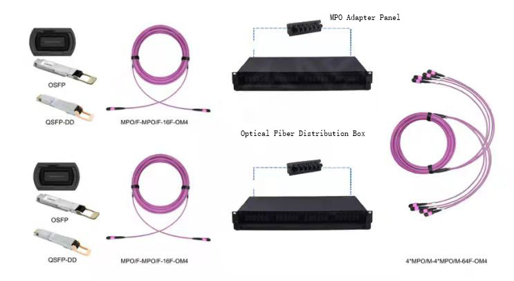
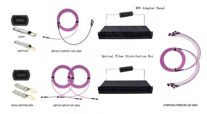
In addition, it is also important to use the correct optical fiber connector in the data center. The optical fiber connector needs to be matched with the optical module. MPO/MTP-8F optical fiber jumper shall be applied to SR4/DR4 connection scheme, and MPO/MTP-16F optical fiber jumper shall be applied to 400G QSFP-DD SR8 connection scheme. At present, 400G optical fiber interface with high market recognition includes 400GBase-SR4.2, 400GBase-DR4, and 400GBase-SR8.
The specific wiring scheme is as follows:
- QSFP-DD 400G DR4 to 400G DR4 connection scheme: an MPO/MTP pre-terminated trunk optical cable is deployed between two 400G switches, an 8-core MPO/MTP optical fiber jumper is deployed at the 400G switch end to connect the 400G DR4 optical module, and a high-density optical fiber distribution box (including MPO adapter) is deployed between the pre-terminated trunk optical cable and the optical fiber jumper for management.
- QSFP-DD 400G SR8 to 400G SR8 connection scheme: an MPO/MTP pre-terminated trunk optical cable is deployed between two 400G switches, a 16-core MPO/MTP optical fiber jumper is deployed at the 400G switch end to connect 400G SR8 optical module, and a high-density optical fiber distribution box (including MPO adapter) is deployed between the pre-terminated trunk optical cable and optical fiber jumper for management.
- QSFP-DD 400G SR8 to 200G QSFP56 SR4 connection scheme: an MPO/MTP pre-terminated backbone optical cable is deployed between two switches, a 16-core MPO-2 * MPO/MTP optical fiber jumper is deployed at 400G switch end to connect 400G transceiver, and 8-core MPO/MTP optical fiber jumper is deployed at 200G switch end, High-density optical fiber distribution box (including MPO adapter) is deployed between pre-terminated trunk optical cables and optical fiber jumpers for management.
Summary
At present, the world’s super large-scale data centers have begun to deploy 400G Ethernet in 2020. It is expected that 400G Ethernet will enter the stage of large-scale deployment in 2022. Datacenter applications, networks, and optical transceivers are evolving rapidly today. The upgrade planning time of each data center will vary according to technical requirements, budget, scale, and business priorities. Opticswave can provide you with a full range of 400G QSFP-DD optical module products including 400G DR4, 400G SR8, 400G FR4, 400G LR4, 400G LR8, etc., to help you realize the transformation and upgrading of the data center faster and better.